The site foundation for a concrete mixing plant is typically covered under civil engineering plans, with its costs and acceptance procedures handled separately from the investment in equipment such as the main mixer, aggregate bins, and control systems. Factors such as the flooring’s load-bearing capacity and the routing of the drainage system directly impact the equipment’s operational history—influencing the frequency of main shaft bearing replacements, the recalibration intervals for batching scales, and the schedule for inspecting anchor bolts for corrosion.
This article details how insufficient load-bearing capacity can lead to abnormal wear on main shaft bearings and accuracy drift in batching scales, and how flaws in drainage design can cause anchor bolt corrosion and moisture-related failures in control cabinets. It also outlines specific details that can be verified during the site planning stage, allowing you to clarify requirements with civil contractors and equipment suppliers before construction drawings are finalized.
How Poor Floor Bearing Capacity Gradually Damages Equipment
Floor load-bearing capacity is often viewed merely as a civil engineering compliance benchmark—once the blueprints are approved and the final inspection passes, the matter is considered settled. In reality, however, the uniformity of load distribution across the site continues to exert a subtle yet persistent influence once the concrete plant is put into operation. Let us start with the main unit and trace, step by step, how uneven foundation bearing capacity transmits its effects—incrementally—to the various components of the equipment.
Main Unit Foundation: The Origin of Differential Settlement
When site bearing capacity is uneven, the settlement state of the main unit foundation itself is often the first to change.
- Differential Settlement: In areas where undisturbed soil and backfill soil are mixed, bearing capacity is inconsistent, making the main unit foundation prone to localized variations in settlement magnitude.
- Shift in Load Angle: Even a height difference of just a few millimeters can cause the load angle on the main shaft and mixing arms to shift.
- Abnormal Bearing Noise: Changes in the load angle cause slight noises during bearing rotation; this is often the earliest detectable signal.
- Seal Wear: Abnormal bearing loading accelerates seal wear beyond the normal service life.
Batching System: Precision Drift Caused by Transmitted Settlement
Subtle changes in the main unit foundation do not stop at the unit itself but extend to the metering components.
- Platform Torsion: The weighing platform supporting the aggregate and cement scales undergoes slight twisting as the foundation settles.
- Calibration Inaccuracy: Weighing system precision relies on the stability of the platform structure; platform torsion causes the calibration baseline to shift.
- Cumulative Data Deviation: Batching data deviations are not isolated incidents but accumulate over months, becoming increasingly pronounced.
- Delayed Detection: Such deviations are often only discovered during quality inspections, by which time the error has already persisted for some time.
Steel Structure Connections: Points of Accumulated Vibration Stress
The main unit generates continuous vibration during operation; ideally, this energy is absorbed by the foundation, but the situation changes when foundation rigidity is insufficient.
- Vibration feedback: When the foundation fails to effectively dissipate dynamic loads, vibrations are transmitted back into the steel structure itself.
- Connection loosening: Prolonged vibration causes bolted connections to gradually loosen.
- Weld fatigue: Repeated stress on welds leads to the formation of microscopic fatigue cracks.
- Hidden nature: Such damage is difficult to detect during routine inspections and often only comes to light during periodic overhauls involving disassembly.
Foundation cracks: A convergence point for load-bearing issues
If insufficient load-bearing capacity persists, the foundation concrete itself may eventually develop hairline cracks.
- Crack formation: Prolonged uneven loading causes hairline cracks to gradually appear on the foundation surface.
- Water ingress: While often overlooked, these cracks serve as pathways for rainwater or accumulated surface water to seep in.
- Corrosion risk: Seeping water contacts the internal reinforcing bars and anchor bolts, triggering gradual corrosion—and anchor bolts are among the components most directly affected by drainage design.
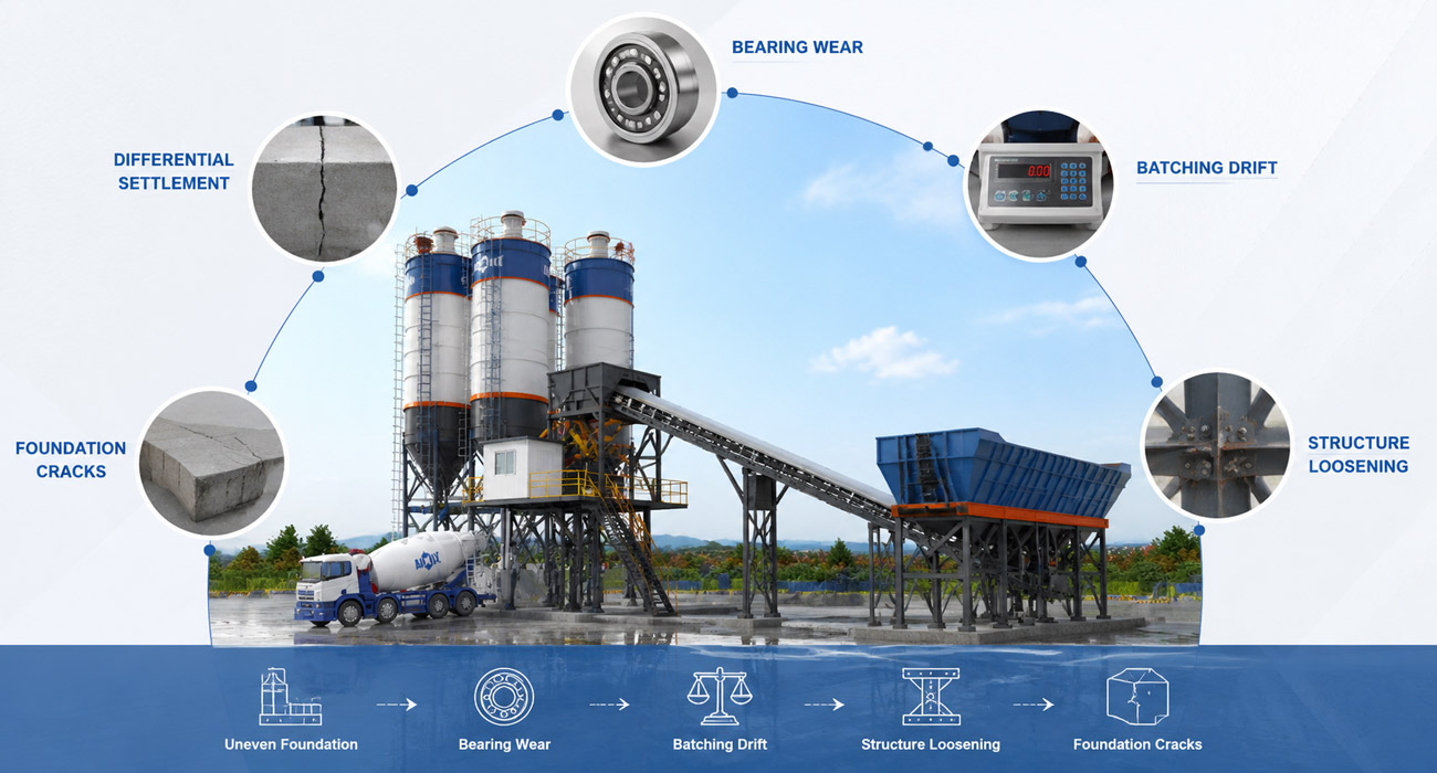
From subtle settlement of the main unit’s foundation and cumulative deviations in batching data to the buildup of fatigue at steel structural connections, these changes rarely occur simultaneously; instead, they manifest sequentially. Precisely for this reason, when load-bearing issues first emerge, they are easily dismissed as normal wear and tear on individual components. However, by the time cracks actually appear in the foundation concrete, the problem extends beyond mere load-bearing capacity: the critical concern shifts to the more direct impact the equipment will suffer once moisture finds a way in.
Site Drainage Design: Water Flow Determines Component Performance
Water seepage through cracks is merely one pathway for moisture to enter the equipment. In fact, from the perspective of overall site planning, the drainage design dictates the flow, accumulation, and seepage patterns of rainwater, aggregate washing wastewater, and process water across the site; if this drainage path is not designed for smooth flow, the consequences will manifest on specific components—more rapidly and directly than issues caused by foundation cracks.
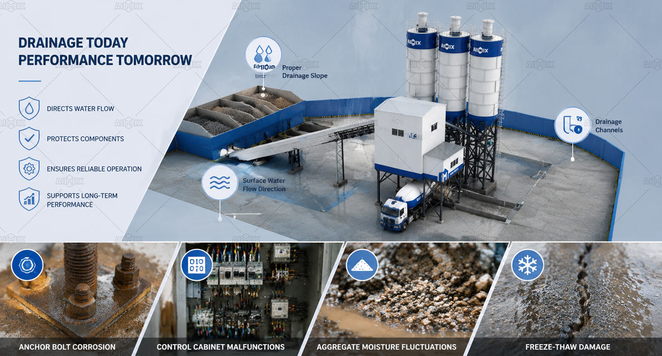
Corrosion Process of Anchor Bolts and Base Plates
Anchor bolts play a critical role in resisting equipment vibration and overturning, yet they are precisely the components most vulnerable to accumulated water.
- Positional Factors: The bases of main units and material silos are often located in the lowest-lying areas of the site; if the slope design fails to channel water away effectively, these spots become prone to water pooling.
- Prolonged Immersion: Compared to brief exposure to rain, long-term immersion accelerates the corrosion of metal components much more significantly.
- Cross-sectional Loss: Over time, accumulated corrosion causes the effective cross-section of the anchor bolts to thin; this deterioration often requires specialized inspection to detect.
- Prevention Measures: The rate at which this occurs depends largely on whether the site slope and drainage channels were designed with the risk of water accumulation around the equipment in mind.
Intermittent Control Cabinet Malfunctions
The placement of control cabinets and power distribution boxes is also linked to drainage pathways.
- Location Selection: If control cabinets are situated in low-lying areas near zones where water accumulates, moisture can more easily seep into the cabinet interiors.
- Component Oxidation: When components such as contactors and relays are exposed to a humid environment for extended periods, their contact points gradually oxidize.
- Fault Characteristics: These malfunctions are typically intermittent—for instance, equipment might fail to start properly on a humid morning but return to normal operation later—making troubleshooting more time-consuming than addressing standard hardware wear.
- Prevention Methods: This risk can be mitigated during the site planning stage by carefully selecting the control room location and elevating the ground level.
Moisture Content Fluctuations in Aggregate Stockpiles
Drainage design also impacts the final quality control of the concrete through a different pathway.
- Water accumulation in the stockpile area: If drainage in the aggregate storage area is inadequate, aggregates may remain in a state of oversaturation for extended periods.
- Impact on mix proportions: Fluctuating aggregate moisture content introduces additional variables into the actual control of the water-cement ratio during the batching process.
- Scope of impact: This issue primarily affects product quality consistency rather than equipment wear, yet it stems directly from the adequacy of the site’s drainage design.
- Room for adjustment: Drainage gradients and protective covering measures in the stockpile area are usually the aspects most easily optimized in advance to address this issue.
Foundation cracking in freeze-thaw climates
If your project is located in an area with significant freeze-thaw cycles, drainage design involves an additional layer of consideration.
- Regional relevance: This part primarily to regions where winter temperatures drop significantly below freezing and repeated freeze-thaw cycles occur.
- Frost heave process: If accumulated water caused by poor drainage seeps into the foundation, the volumetric expansion that occurs when the water freezes in winter exerts additional stress on the concrete.
- Risk of cracking: This repeated freeze-thaw action can accelerate the onset of cracking in the foundation.
- Regional recommendations: For projects in such climatic zones, frost protection measures typically require specific consideration during the drainage design phase, rather than relying on a standard, one-size-fits-all approach.
From anchor bolt corrosion and intermittent control cabinet malfunctions to fluctuations in aggregate moisture content—these issues follow different paths of development, yet they all stem from the same origin: whether the site drainage design provided a proper outlet for water flow during the initial planning stage. Much like issues regarding load-bearing capacity, these problems tend to emerge gradually rather than appearing immediately upon commissioning; this is precisely why drainage design often fails to receive due attention until the concrete batching plant business plan has been in operation for some time.
Foundation Design Standards: Bearing Capacity & Drainage Guidelines
The underlying causes of the issues previously discussed—main unit tilting, weighing inaccuracies, anchor bolt corrosion, and moisture ingress in control cabinets—can essentially be attributed to a single type of problem: a failure in the foundation design process to adequately account for the equipment’s actual operating conditions. While foundation design involves a wide range of factors, given that this article focuses on load-bearing capacity and drainage, we will outline key points regarding these two aspects that can serve as criteria for assessment.
Load-bearing Capacity Design: Ensuring consistent load distribution across the site
- Zonal load assessment: Evaluate actual loads separately for the main plant platform, cement silos, and aggregate bins, rather than applying a single load-bearing standard to the entire site.
- Prioritizing geotechnical surveys: Conduct site-wide geotechnical surveys before finalizing foundation plans to identify the distribution of undisturbed soil versus fill material.
- Targeted foundation treatment: Implement specific measures—such as soil replacement or compaction—for areas with insufficient or uneven load-bearing capacity, rather than simply raising the safety factor across the board on the blueprints.
- Provisions for settlement monitoring: Incorporate settlement observation points into the design for critical equipment foundations to facilitate periodic status checks after commissioning.
- Early acquisition of equipment point-load data: Obtain specific parameters—such as point loads and vibration frequencies—directly from equipment manufacturers before designing foundations, rather than relying on generic estimates.
Drainage Design: Ensuring a clear, designated path for water flow
- Site-wide grading plan: Establish a unified slope across the site—from the main plant and silos to the stockpile area—to direct runoff into collection channels, preventing the formation of scattered low-lying pools around the equipment.
- Localized elevation for equipment areas: Elevate moisture-sensitive components (such as control cabinets and power distribution boxes) above the general site grade to isolate them from surrounding drainage paths.
- Separate designs for collection and sedimentation: Plan distinct collection routes for process wastewater and rainwater to prevent wastewater containing aggregate fines or cement slurry from stagnating around equipment foundations.
- Climate-adaptive adjustments: Incorporate freeze protection measures into the drainage plan for regions subject to freeze-thaw cycles.
- Maintenance access provisions: Designate access paths along drainage channels and pipes to facilitate the periodic removal of accumulated sediment, preventing a decline in drainage efficiency over time.
The core logic behind these points essentially points to the same conclusion: if the actual operating conditions of the equipment are factored into the initial design, most of the progressive wear and corrosion issues encountered during subsequent operation can be avoided. In other words, the standards themselves are not complex; the key lies in whether they were taken seriously during the concrete ready mix plant site planning stage.
Turning Standards into Action: Key Questions for Suppliers
The standards themselves are not complex, but their successful implementation depends largely on whether the equipment manufacturer and the civil engineering team are aligned—for instance, whether the civil engineering team has received the equipment’s point-load data, and whether the drainage path design accounts for the actual equipment layout. You can use the following questions to communicate directly with concrete batching plants manufacturers during the project’s early stages and verify that this information has been properly conveyed.
Have the point load and vibration parameters of the equipment been provided to the civil engineering contractor?
- Your requirement: When designing the foundation, the civil engineering contractor needs the actual point load distribution and vibration frequencies of the equipment, rather than generic empirical values.
- Supplier should provide: Technical documentation (pre-shipment) containing load data for key components—such as the main unit and storage silos—that can be directly used by the civil engineering contractor as input for the foundation design.
Have the foundation requirements for different parts of the equipment been specified separately?
- Your requirement: Foundation requirements differ for the main unit platform, cement silos, and aggregate bins; these need to be confirmed individually rather than handled under a single, generalized standard.
- Supplier should provide: Foundation design recommendations or drawing annotations tailored to specific equipment sections, detailing requirements for load-bearing capacity and surface flatness.
Are the locations of drainage interfaces clearly marked on the drawings?
- Your requirement: Drainage paths for moisture-sensitive components (such as control cabinets and power distribution boxes) must be determined during the site master planning stage, rather than adjusted ad-hoc during equipment installation.
- Supplier should provide: Equipment layout drawings that clearly mark locations requiring avoidance of standing water or the provision of drainage slopes.
Does the anchoring plan account for the equipment’s actual vibration characteristics?
- Your requirement: Anchor bolt layout and embedment depth must match the equipment’s actual vibration profile, rather than relying on a generic anchoring standard.
- Supplier should provide: Anchoring recommendations specific to the equipment model, including suggested anchor bolt specifications and spacing.
Is there an acceptance process to verify compliance after the on-site foundation is completed?
- Your requirement: Before formal installation, the actual condition of the foundation (e.g., levelness, slope) must be verified against design specifications to prevent discovering issues only after installation.
- Supplier should provide: A pre-installation site foundation inspection service or a clear checklist of acceptance criteria for the civil engineering contractor to use for self-inspection.
Fundamentally, these five questions all seek to confirm the same thing: whether the information required regarding the equipment and the foundation has been clearly and effectively communicated between the civil works contractor and the supplier. Often, the root cause of foundation-related issues is not complex; it simply stems from the fact that the relevant information was not fully aligned during the early stages of the project.
AIMIX Solves These Early in the Project Phase
By now, you might be wondering: will this information be provided proactively, or do I have to ask for each item individually? This is precisely the point we want to clarify: details such as point load data, foundation requirements for specific zones, drainage connection points, anchoring plans, and on-site acceptance protocols are not extra services provided only upon request within the AIMIX project workflow; rather, they are standard components prepared well before equipment delivery. Let us explain exactly how we handle each of these aspects.
Design Phase: Provision of Detailed Equipment Specifications
- Load and Vibration Data: Point load and vibration frequency parameters for key components—such as the main unit and storage silos—are included in the technical documentation. These are provided directly to the civil engineering team as input for foundation design, eliminating the need for you to request them separately or estimate them yourself.
- Section-Specific Foundation Recommendations: Foundation design recommendations are provided separately for the main unit platform, cement silos, and aggregate bins. Specific requirements regarding load-bearing capacity and surface flatness are detailed for each section, rather than providing a generic drawing applicable to the entire site.
- Drainage Location Marking: The general equipment layout plan marks the precise locations of moisture-sensitive components (such as control cabinets and power distribution boxes). This allows the civil engineering team to plan drainage paths that avoid these areas or incorporate appropriate slopes in advance.
Construction Phase: Seamless Information Flow
- Anchoring Recommendations: Recommendations for anchor bolt specifications and spacing are provided based on the specific equipment model and its vibration characteristics, rather than relying on a generic installation manual.
- Direct Technical Liaison: If the civil engineering team has questions regarding equipment parameters during construction, they can communicate directly with the AIMIX technical team for clarification.
- Climate-Specific Guidance: Guidance on foundation design is provided for regions with challenging climates—such as areas prone to freeze-thaw cycles or high humidity—helping the civil engineering team account for local climatic requirements early on.
Installation Phase: Foundation Verification Prior to Equipment Arrival
- On-Site Foundation Inspection: A foundation inspection service is provided before formal installation begins. This verifies that actual site conditions—such as levelness and slope—meet design specifications, allowing for timely adjustments before installation starts and preventing issues discovered only after the equipment has arrived.
- Inspection Feedback: If the inspection reveals discrepancies between the foundation status and design requirements, a detailed report is issued so the civil engineering team can make necessary adjustments before equipment installation.
- Coordinated Scheduling: Equipment installation is scheduled only after the foundation passes inspection, preventing misalignment between foundation work and the installation timeline.
The combined result of these steps is that key information required for foundation design—derived from equipment specifications, layout drawings, and on-site verification—is delivered well in advance. This eliminates the need for ad-hoc coordination during the project and enables the civil engineering team to base their work on accurate equipment parameters right from the design stage.
For AIMIX, this represents a standardized delivery process refined through long-term experience with projects across diverse climatic zones and geological conditions; we believe that clearly communicating foundation-related information early on is the more reliable approach.
FAQs
Do concrete mixing plants of different capacities have the same requirements for flooring load-bearing capacity?
Should the design of the drainage system be the responsibility of the civil engineering contractor or the equipment manufacturer?
For an existing site already in operation, how can one determine if the current foundation meets the necessary standards?
If foundation issues have already arisen, is there room for remediation, or is prevention the only option?
Can I contact AIMIX directly during the early stages of the project for advice on foundation design?
Will ensuring adequate load-bearing capacity and drainage significantly increase the project budget?
How long does the foundation design process typically take, and will it delay the overall project schedule?
Foundations Are Invisible, But Performance Differences Are Visible
Most discussions regarding concrete mixing plants focus on parameters that are visible and directly comparable—such as the performance of the main mixer, batching accuracy, and production capacity. However, the ability to maintain consistent performance over the long term depends heavily on the foundation beneath the equipment; while this element does not appear in technical specification sheets, its impact is continuously reflected in every visible performance metric during day-to-day operations. Addressing load-bearing capacity and drainage requirements during the project’s initial planning stage is essentially a way of securing an insurance policy for the entire equipment investment.